 Kia Sportage: Components and Components Location
Third generation SL (2010ŌĆō2016) / Kia Sportage SL Service & Repair Manual / Engine Control / Fuel System / Engine Control System / Components and Components Location
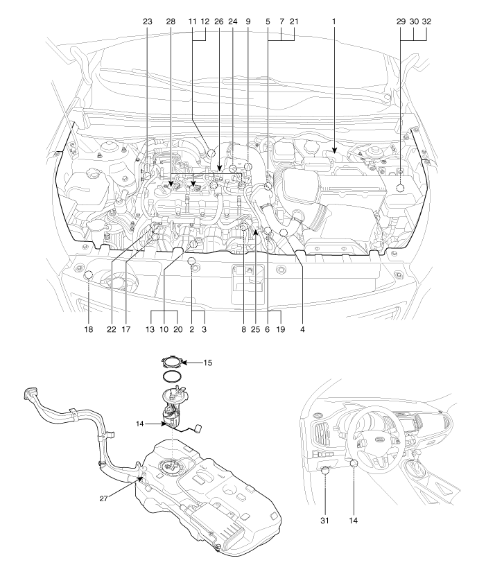
| Components Location |

| 1. Engine Control Module (ECM) 2. Manifold Absolute Pressure Sensor (MAPS) #1 3. Intake Air Temperature Sensor (IATS) 4. Manifold Absolute Pressure Sensor (MAPS) #2 5. Engine Coolant Temperature Sensor (ECTS) 6. Throttle Position Sensor (TPS) [integrated into ETC Module] 7. Crankshaft Position Sensor (CKPS) 8. Camshaft Position Sensor (CMPS) [Bank 1 / Intake] 9. Camshaft Position Sensor (CMPS) [Bank 1 / Exhaust] 10. Knock Sensor (KS) 11. Heated Oxygen Sensor (HO2S) [Bank 1 / Sensor 1] 12. Heated Oxygen Sensor (HO2S) [Bank 1 / Sensor 2] 13. Rail Pressure Sensor (RPS) 14. Accelerator Position Sensor (APS) 15. Fuel Tank Pressure Sensor (FTPS) 16. Fuel Level Sensor (FLS) | 17. CVVT Oil Temperature Sensor (OTS) 18. A/C Pressure Transducer (APT) 19. ETC Motor [integrated into ETC Module] 20. Injector 21. Purge Control Solenoid Valve (PCSV) 22. CVVT Oil Control Valve (OCV) [Bank 1 / Intake] 23. CVVT Oil Control Valve (OCV) [Bank 1 / Exhaust] 24. Electric Waste Gate Actuator (EWGA) 25. RCV Control Solenoid Valve 26. Fuel Pressure Regulator Valve 27. Canister Close Valve (CCV) 28. Ignition Coil 29. Main Relay 30. Fuel Pump Relay 31. Data Link Connector (DLC) [16-Pin] 32. Multi-Purpose Check Connector [20-Pin] |
| 1. Engine Control Module (ECM) | 2. Manifold Absolute Pressure Sensor (MAPS) #1 3. Intake Air Temperature Sensor (IATS) |
|
|
| 4. Manifold Absolute Pressure Sensor (MAPS) #2 | 5. Engine Coolant Temperature Sensor (ECTS) |
|
|
| 6. Throttle Position Sensor (TPS) 19. ETC Motor | 7. Crankshaft Position Sensor (CKPS) |
|
|
| 8. Camshaft Position Sensor (CMPS) [Bank 1 / Intake] | 9. Camshaft Position Sensor (CMPS) [Bank 1 / Exhaust] |
|
|
| 10. Knock Sensor (KS) | 11. Heated Oxygen Sensor (HO2S) [Bank 1/Sensor 1] |
|
|
| 12. Heated Oxygen Sensor (HO2S) [Bank 1/Sensor 2] | 13. Rail Pressure Sensor (RPS) 20. Injector |
|
|
| 14. Accelerator Position Sensor (APS) | 15. Fuel Tank Pressure Sensor (FTPS) |
|
|
| 16. Fuel Level Sensor (FLS) | 17. CVVT Oil Temperature Sensor (OTS) 22. CVVT Oil Control Valve (OCV) [Bank 1 / Intake] |
|
|
| 18. A/C Pressure Transducer (APT) | 21. Purge Control Solenoid Valve (PCSV) |
|
|
| 23. CVVT Oil Control Valve (OCV) [Bank 1 / Exhaust] | 24. Electric Waste Gate Actuator (EWGA) |
|
|
| 25. RCV Control Solenoid Valve | 26. Fuel Pressure Regulator Valve |
|
|
| 27. Canister Close Valve (CCV) | 28. Ignition Coil |
|
|
| 29. Main Relay 30. Fuel Pump Relay 32. Multi-Purpose Check Connector [20-Pin] | 31. Data Link Connector (DLC) [16-Pin] |
|
|
 Description and Operation
OBD-II review
1. Overview
The California Air Resources Board (CARB) began regulation of
On Board Diagnostics (OBD) for vehicles sold in California beginning
with the 1988 model year. The first ...
 Engine Control Module (ECM): Schematic Diagrams
ECM Terminal And Input/Output signal
ECM Terminal Function
Connector [CHTG-AG]
PinNo.DescriptionConnected to1Ignition Coil (Cylinder #2) control output [Without Smart Key]Ignition Coil (Cylin ...
Other Information:
Troubleshooting
Engine Overheat Troubleshooting
Inspection RemedyVisual inspectionInspect for shortage of coolant in reservoir tank .Reinspect after replenishing coolant.Inspect for coolant pollution after remo ...
Mode selection
The mode selection button controls the direction of the air flow through the
ventilation system.
The air flow outlet port is converted as follows:
Refer to the illustration in the ŌĆ£Manual cl ...
Categories
- Home
- Kia Sportage QL (2015-2019) Owners Manual
- Kia Sportage QL (2015-2019) Service Manual
- Kia Sportage SL 2010-2016 Owners Manual
- Kia Sportage SL 2010-2016 Service Manual
Copyright ® www.kispmanual.com 2014-2025


